The HDMI board I bought before reading the datasheet
The plan for getting the console onto a TV was meant to be the easy part. The STM32H753 has an LTDC, a hardware display controller that scans a framebuffer out of RAM as parallel RGB with no CPU per frame. The H7 has no HDMI of its own, but parallel RGB into a cheap RGB888-to-HDMI converter board, out an HDMI cable, into any monitor, is a well-trodden path. So I found a Geekworm 50-pin RGB888-to-HDMI board for about $28 and bought it off AliExpress.
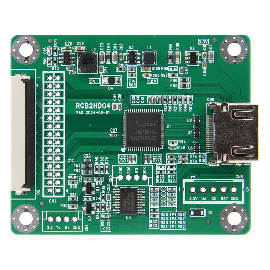
Then I sat down to wire it up, and counted the pins.
RGB888 needs 24 wires the Nucleo does not have
RGB888 is 24 data lines: 8 red, 8 green, 8 blue. Plus HSYNC, VSYNC, DE, and the pixel clock. 28 signals, all of which have to come out of the Nucleo's headers on specific pins, because the LTDC's outputs are fixed in silicon to particular GPIOs.
Most of them are fine. Two of them are not, and the two that are not have exactly one possible pin each:
LTDC_R0has one pin in the whole package: PG13. On this board PG13 is the Ethernet RMII TXD0, wired to the onboard LAN8742 PHY.LTDC_R1has one pin: PA2. That is the Ethernet RMII MDIO.
There is no second choice for either. If I want the bottom two bits of red, I lose Ethernet. And it gets worse, because three more of the data lines land on pins I am already using for sound:
LTDC_G0is PE5,LTDC_G1is PE6,LTDC_B0is PE4. Those three are the SAI1 audio bus driving the PCM5102A DAC, which is very much live.
So full RGB888 is not a layout I have to be clever about. It is a thing the chip physically cannot do on this board without giving up either the network or the audio. I had bought a board for a colour depth the Nucleo cannot produce.
RGB666 is the exact subset that dodges both
There is a way out, and the nice part is that it is not a compromise so much as a coincidence. Drop the two least-significant bits of each colour channel - use R2-7, G2-7, B2-7 - and you get RGB666, 18-bit colour. Look at which bits that throws away:
- It drops R0 and R1. That is exactly the pair stuck on the Ethernet pins.
- It drops G0, G1, and B0. That is exactly the trio stuck on the audio pins.
RGB666 is not an arbitrary downgrade to make the wiring fit. It is the precise set of bits that removes every conflicting pin and nothing else. Ethernet stays, audio stays, and 18bpp is a standard HDMI colour depth anyway. For a console running a 16-colour PICO-8 palette, the visible loss is nil - the framebuffer is still 8bpp into a 256-entry palette where each entry is a full 24-bit colour; it is only the output bus that carries six bits per channel instead of eight.
So I wrote the first-light firmware for it. There is an hdmi cargo feature in
firmware/src/hdmi.rs that brings up the LTDC at 640x480p60, generates a 25 MHz
pixel clock off PLL3 (64 MHz HSI / 4, times 50, divided by 32 = 25.0 MHz, close
enough to the 25.175 standard for ~59.5 Hz refresh), maps 22 GPIOs to the RGB666
bus, and paints colour bars. It compiles. It has never been near a monitor.
The board works. The wiring is the problem.
Here is the thing I keep coming back to. The Geekworm board is fine. The RGB666 plan is sound, and since I own the board I am going to bring it up regardless, because driving the LTDC at a real video mode is exactly the code the proper mainboard will reuse later. It is worth doing.
But the way you drive it from a bare Nucleo is 22 dupont jumpers carrying a 25 MHz bus from header pins to a converter board. Twenty-two. Each one a chance for a flaky contact or a bit of crosstalk, all of them switching at 25 MHz over wires that were never meant to be a parallel video bus. That is not a setup I trust, and it is not one I want to debug.
Which got me asking a different question. What if HDMI is not the H7's job at all?
Hand the whole problem to a second chip
There is a microcontroller that is genuinely good at HDMI for almost no money: the RP2040. The PicoDVI project (Luke Wren's bit-banged DVI) makes an RP2040 generate a real DVI signal using its PIO state machines and a brutal overclock, on eight GPIO pins. DVI plugs straight into any HDMI monitor with a passive adapter.
So the shape becomes this. The H7 does not touch a single video pin. It streams its framebuffer over SPI to an RP2040, and the RP2040 is the display adapter - it holds the pixels and emits the HDMI itself.
  STM32H753 (the console)                RP2040 (the display adapter)
  framebuffer + present loop  --SPI-->   receive frame -> PicoDVI --HDMI--> TV
  ~4 pins, no parallel bus               8 GPIO does the TMDS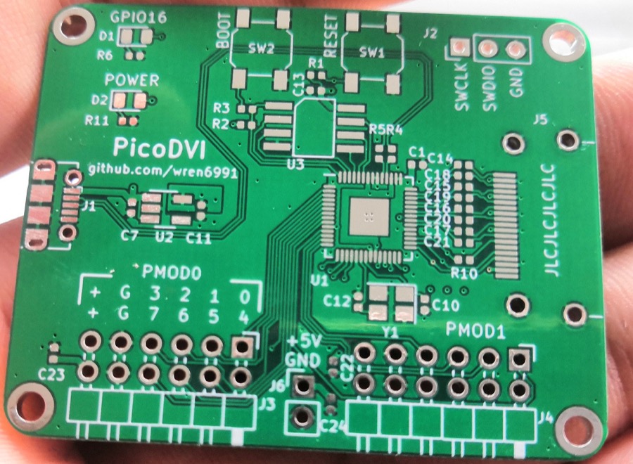
The H7 side costs about four pins instead of twenty-two: SPI clock and data, a chip select, and one line back for vsync. None of them are Ethernet or audio pins. And almost none of it is new code, because I already built the hard part. The SPI panel that drives the little ST7735 already DMAs an RGB565 framebuffer out SPI1 without the CPU babysitting it. To the H7, the RP2040 just looks like another panel on the end of that same DMA. Better still, PicoDVI's internal framebuffer is RGB565, which is the exact format that panel path already produces.
It is also not a new idea in this project, just a new endpoint. The framebuffer already streams to the Mac viewer over USB, and there is a parked path that streams it to a cheap ESP32 LCD board over UART. The protocol does not care what is on the other end. An RP2040 driving HDMI is simply the next thing that reads the stream.
The cooler version of this does not even send raw pixels. Instead of shipping a whole screen every frame, the H7 could send the RP2040 commands - set the palette, upload a tileset, draw this sprite here, draw that text there, present - and let the RP2040 keep the framebuffer and do the blitting. That is far less traffic over the link and a lot more like a real console's video chip than a dumb frame pipe. The important part, either way, is the boundary: the RP2040 is only ever the display chip. It owns the framebuffer and the HDMI and nothing else. The H7 stays the brain
- the OS, the VM, input, storage, audio, the game. PicoDVI already uses most of the little chip, so the rule writes itself: if a job tempts the RP2040 toward running part of the console, it belongs on the H7.
And then I bought a second board
I would love to tell you I learned my lesson about buying hardware before checking it works. Instead, while writing this, I ordered an Adafruit Feather RP2040 with DVI output for about $30 from Little Bird. It is an RP2040 with an HDMI connector wired for DVI and the PicoDVI library ready to go. The one real constraint is memory: 264 KB of SRAM, and generating the DVI signal already spends 150-190 KB of it. A 320x240 framebuffer is 153,600 bytes at 16-bit colour but only 76,800 at 8-bit, so the trick is to keep the framebuffer 8-bit and paletted - which is exactly the format the console already uses internally. A 16-bit double-buffer would not fit; an 8-bit single buffer does, with room to spare for the link. It is DVI only, no audio over the HDMI, but for a bench display that is fine.
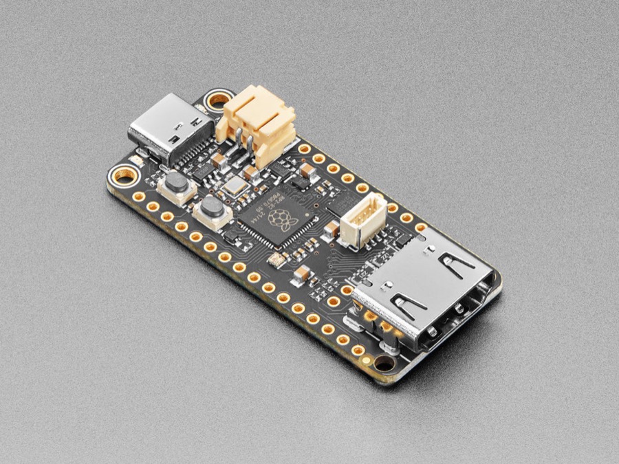
So I now own two HDMI boards and have tested exactly zero of them. The plan from here is honest about that: bring up the Geekworm RGB666 path because I already have it and it exercises the LTDC, then try the cleaner co-processor path on the Feather. Further out, the real console mainboard uses a proper HDMI transmitter (an SiI9022A) that carries the game audio inside the HDMI cable, which neither of these bench boards can do.
The lesson, such as it is: the LTDC datasheet table that lists which pin each colour bit can use is free to read, and I read it one board too late. Count the pins before you check out.
The full design for the co-processor path - the link options, the bandwidth maths, the SRAM budget on the RP2040, and the tearing risk - is written up in more detail than this post has room for. That writeup lives in the project repo, which is private for now and might open up once the whole thing is finished. Now I just have to wait for the post.
Once the Feather lands I can finally stop describing this console in adjectives and start showing it: real video of the actual device, menus and carts and all, straight off the HDMI port. The order is in. The letterbox is being watched.
Update, 3rd July 2026: it arrived - and lit up the same day. First light, two ambushes and the whole smoke test are in Sixteen bars and a bouncing box.
Image credits: the RGB888-to-HDMI board photo is from Geekworm; the Feather RP2040 DVI photo is from Little Bird Electronics; the PicoDVI board photo is from the PicoDVI project by Luke Wren.