First light on the Feather RP2040 DVI
Three days ago I wrote about the HDMI board I bought before reading the datasheet - the 50-pin RGB888 converter the Nucleo could never actually drive, and the plan B that came out of it: a $30 Adafruit Feather RP2040 DVI as a video co-processor. The H7 keeps being the console; the RP2040's whole job is to take frames over a four-wire SPI link and bit-bang them out an HDMI connector using PicoDVI.
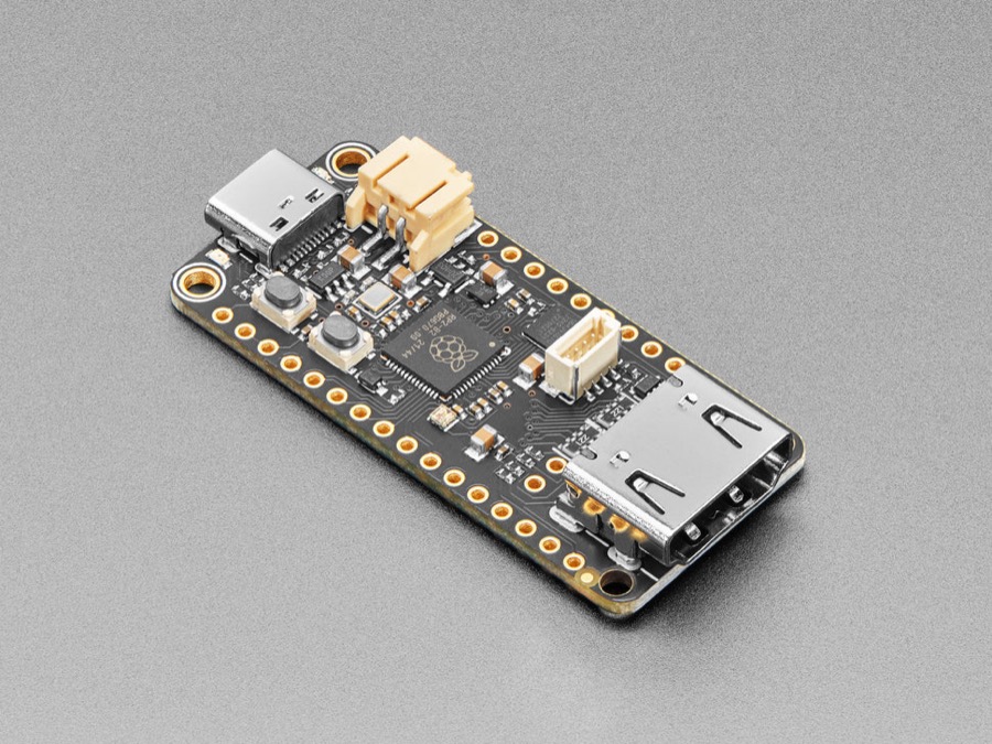
The Feather RP2040 DVI arrived at 9:46 this morning, sharing the parcel with the W25Q128JV flash chips from the cartridge-slot experiment - a good post day for the letterbox. The morning went to the console's search feature, so the Feather got its turn just before noon; by 12:32pm it was drawing the console's sixteen PICO-8 colours as bars on a monitor, with a white box bouncing over them.
That clip is a pixel-exact re-render of what the smoke test puts in the framebuffer (the demo is deterministic, so the frames can be reproduced byte-for-byte off-device). The real monitor shows one thing the clip cannot, and it matters later in this post. The rest is about the 45 minutes in between, because none of it went the way the plan said, and all of it was cheaper to learn on day one than mid-integration.
The wrong board's diagram
The wiring plan was already drawn: the H7 gives up four pins (SPI5 SCK on PF7, MOSI on PF9, a CS GPIO on PF8, and PE2 listening for vsync coming back), all on CN9, all clear of the panel, the audio bus, and Ethernet. The Feather side of the link is the silk pins SCK, MI, D9 and D10 - one hardware SPI1 slave group.
Before touching a jumper I cross-checked the wiring table against the Feather pinout diagrams saved in the repo - and they disagreed. The diagrams put SCK, MO and MI on GP18, GP19 and GP20. The table said GP14, GP15 and GP8.
Both were right. The saved diagrams were for the plain Feather RP2040 - product 4884. The board on the bench is the DVI variant - product 5710 - and Adafruit quietly remapped the SPI pins on it, because the DVI connector consumes GP16 through GP23 for the TMDS pairs, which is exactly where the plain board keeps its SPI block. Same silk labels, different silicon underneath. On the DVI variant, D9 is not just a GPIO that happens to be free; it is literally SPI1 CSn.
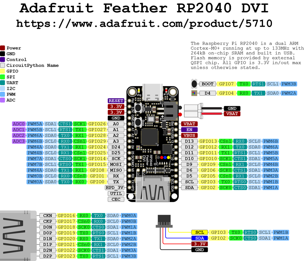
The practical rules that came out of this: wire by the silk names and both boards agree; write firmware pin constants only from the variant's own diagram; and keep the correct diagrams in the repo so the wrong ones cannot ambush anyone again. The docs now carry the warning and the 5710 images.
The firmware that wasn't there
Day-one testing philosophy: neither side of the SPI link exists yet - the H7
PicoDviStream backend and the RP2040 receiver are designed on paper only - so
wiring the link today would produce exactly nothing. The only test that can put
pixels on a screen is a standalone one: flash the Feather with something that
draws, and prove board + cable + monitor before writing a line of link firmware.
The smoke test is fifteen lines of scene setup and a loop: bring up the 320x240
DVI output, draw the sixteen PICO-8 palette colours as vertical bars, bounce a
white box over them (the full listing is at the end of this post). Using the
console's own palette was deliberate - the smoke test doubles as a colour check
for the day real frames flow. Under CircuitPython's picodvi module sits
PicoDVI, the bit-banged DVI project that
overclocks the RP2040 to ~252 MHz and drives the TMDS pairs from its PIO
blocks - the previous post covers why that is the whole reason this board
exists.
Plugged in, the board enumerated as "Feather RP2040 DVI" with a serial port - and
no CIRCUITPY drive. The factory firmware is a test app, not CircuitPython. So:
hold BOOTSEL, replug, and an RPI-RP2 drive appears; drop the CircuitPython 10.2.1
UF2 on it (1.8 MB, 3517 blocks); the board reboots, formats its little
filesystem, and comes back as CIRCUITPY. Copy the smoke test on as code.py.
The monitor showed a console. Not my bars - CircuitPython renders its serial
console out the DVI port by default, which is a genuinely great feature (the
display path was already proven at this point) and also not what I asked for. The
board had run the factory-default code.py - "Hello World!", then "Code done
running" - because my copy raced its first boot. One Ctrl-D down the serial port
soft-reloads, and there they were: sixteen bars, one bouncing box.
M105M105M105M105
Then it went back to the console. On the screen, in the traceback: a
KeyboardInterrupt at line 86 - the time.sleep in my bounce loop. That one was
me; a diagnostic I sent down the REPL to check on it carried a Ctrl-C.
But the REPL was also filling up with this:
>>> M105M105M105M105M105M105
NameError: name 'M105M105' is not defined
M105 is G-code. It is Marlin's "report temperature". Something on the Mac had
decided my display co-processor was a 3D printer and was politely asking it, over
and over, how hot its hotend was.
$ lsof /dev/cu.usbmodem11201
COMMAND   PID   USER   FD   TYPE DEVICE SIZE/OFF NODE NAME
UltiMaker 721 fulvio   36u   CHR   9,17    0t498 1245 /dev/cu.usbmodem11201
UltiMaker Cura, running quietly since the night before, probes every new usbmodem device on the system as a potential printer and holds the port while it polls. It also explains the "multiple access on port" error my own serial script had thrown earlier and that I had shrugged off. Quit Cura, one clean Ctrl-D, and the bars have been up ever since, with nothing typing over them.
New bench rule, filed permanently: when a serial device misbehaves, lsof the
port before blaming the firmware. Cura will grab the console's own CDC port just
as happily as the Feather's.
What first light actually proves
Not much, honestly - and exactly enough. The DVI output works, the cable works,
the monitor negotiates the 640x480 mode PicoDVI generates from a pixel-doubled
320x240 framebuffer, and CircuitPython's picodvi module drives it all from a
default board setup with no soldering and no configuration. Board, cable, monitor:
three variables eliminated before the real work starts.
First light also handed over one bug report, free of charge: the bouncing box tears. The loop moves it whenever it likes, with no locking to the DVI scanout, so every so often the box splits along a scanline mid-flight. That is not a smoke-test bug to fix - it is the exact phenomenon the link design already budgets a wire for. The fifth wire in the plan runs from the Feather's D10 back to PE2 on the H7 so the console can pace its frame pushes to the scanout instead of writing into a framebuffer while it is being read. The demo demonstrated the problem three firmwares before the fix exists.
The real work is the link. Next on the RP2040: a small firmware that sits as an
SPI slave (RX on GP8, clock on GP14, CS on GP9 - the DVI variant's numbers) and
DMAs incoming frames into a paletted 8bpp framebuffer for PicoDVI to scan out.
8bpp is not a stylistic choice: PicoDVI's DVI generation already eats one core,
both PIO blocks and most of the RP2040's 264 KB of SRAM, and a 16bpp 320x240
double-buffer alone would overrun the chip. One byte per pixel plus a 256-entry
CLUT is what fits - and it happens to be exactly the format the console's
framebuffer already uses. Next on the H7: a Present backend that treats the
Feather the way it already treats the SPI panel - a double-buffered DMA blit,
just pointed at different wires.
If you have this board, here is the whole smoke test - drop it on the CIRCUITPY
drive as code.py and you get first light in one file copy (no libraries
needed, built-ins only):
import time
import board
import displayio

display = getattr(board, "DISPLAY", None)
if display is None:
    import framebufferio
    import picodvi

    displayio.release_displays()
    fb = picodvi.Framebuffer(
        320, 240,
        clk_dp=board.CKP, clk_dn=board.CKN,
        red_dp=board.D0P, red_dn=board.D0N,
        green_dp=board.D1P, green_dn=board.D1N,
        blue_dp=board.D2P, blue_dn=board.D2N,
        color_depth=8,
    )
    display = framebufferio.FramebufferDisplay(fb)

import vectorio

PICO8 = [
    0x000000, 0x1D2B53, 0x7E2553, 0x008751,
    0xAB5236, 0x5F574F, 0xC2C3C7, 0xFFF1E8,
    0xFF004D, 0xFFA300, 0xFFEC27, 0x00E436,
    0x29ADFF, 0x83769C, 0xFF77A8, 0xFFCCAA,
]

palette = displayio.Palette(len(PICO8))
for i, c in enumerate(PICO8):
    palette[i] = c

W, H = display.width, display.height
group = displayio.Group()
bar_w = W // len(PICO8)
for i in range(len(PICO8)):
    group.append(
        vectorio.Rectangle(
            pixel_shader=palette, color_index=i,
            width=bar_w, height=H, x=i * bar_w, y=0,
        )
    )

SIZE = 24
box = vectorio.Rectangle(
    pixel_shader=palette, color_index=7, width=SIZE, height=SIZE, x=20, y=20
)
group.append(box)

try:
    display.root_group = group
except AttributeError:
    display.show(group)

x, y, dx, dy = 20, 20, 3, 2
while True:
    x += dx
    y += dy
    if x <= 0 or x >= W - SIZE:
        dx = -dx
        x += dx
    if y <= 0 or y >= H - SIZE:
        dy = -dy
        y += dy
    box.x = x
    box.y = y
    time.sleep(0.016)
The console is one link firmware away from a TV.