A 3x palette scanout for the HDMI picture
Rusty Nail's HDMI path is a two-chip arrangement: the STM32H7 runs the PICO-8 console and streams its 128x128 framebuffer over SPI to an Adafruit Feather RP2040 DVI, which generates the video with PicoDVI. That link has been solid for over a week now (the bring-up story and the first bars are earlier posts), and the console runs games on a 1440p monitor at 59fps.
It also looked grainy. Not broken, not smeared in motion - just soft, in the way that is hard to unsee once you have PICO-8 running in a browser tab on the same monitor for comparison. The browser version has knife-edge pixels. Mine looked like it had been through a photocopier once.
The signal was never the problem
My first suspicion was scaling somewhere in the chain, so I audited it end to end. The audit came back clean: the 128x128 frame goes over the wire 1:1, the RP2040 centres it in a 320x240 framebuffer, and PicoDVI pixel-doubles that to 640x480. Every stage integer, no filtering anywhere. A 128-pixel console line becomes exactly 256 signal pixels.
That "exactly 256" is the problem. The active image is 256x256 inside a 640x480 signal, and the monitor stretches the whole raster to its panel. A 2560x1440 monitor showing 640x480 at the correct aspect scales it to 1920x1440 - exactly 3x, which is the lucky case - but it scales with a bilinear filter, and bilinear at 3x still smears every edge across a band of panel pixels. The arithmetic of how visible that smear is:
console px  ->  N x N signal px  ->  x3 panel scale  ->  3N x 3N panel px
blur band   ~=  1 signal px      ->  ~3 panel px, regardless of N

blur as a fraction of the pixel:  1/N
  v2:  N = 2  ->  a console pixel is 6x6 panel px, its edge band is half a pixel wide
  v3:  N = 3  ->  9x9 panel px, edge band a third of a pixel
The monitor's blur is fixed-size; the only lever on this side of the cable is making the pixel bigger relative to it. Here is the whole effect, simulated (console pixels -> N x N signal blocks -> the panel's bilinear 3x, both shown at the same physical size):
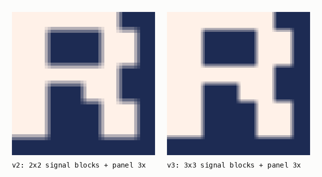
So the goal became: 3x3 signal pixels per console pixel, without changing the proven 640x480p60 timing or the 252MHz clock.
Full-resolution palette encode
The old scanout used PicoDVI's stock dvi_scanbuf_main_8bpp, which
pixel-doubles horizontally by design - it cannot do 3x. But the library has a
better path hiding in its vista-palette demo: tmds_encode_palette_data,
a full-resolution encoder that turns a row of 8-bit palette indices into TMDS
symbols for all three channels, one symbol per pixel, in a single call. Pair
it with DVI_VERTICAL_REPEAT=3 (480/3 = 160 logical rows; the repeat divides
evenly, the library takes it happily) and the geometry falls out: expand each
wire byte to 3 bytes in a 640-wide framebuffer row, and the display shows a
384x384 image, every console pixel a 3x3 block.
The wire format did not change at all. The H7 already sends RGB332 bytes, and an RGB332 byte is just an 8-bit number - so it can be a palette index. Build a 256-entry palette where every slot holds the generic 3-3-2 expansion, then overwrite the 32 slots the console actually emits with the exact PICO-8 RGB888 colours:
static void setup_tmds_palette(void) {
    static uint32_t pal24[256];
    for (uint32_t i = 0; i < 256; i++) {
        uint32_t r = ((i >> 5) & 7) * 255 / 7;
        uint32_t g = ((i >> 2) & 7) * 255 / 7;
        uint32_t b = (i & 3) * 255 / 3;
        pal24[i] = (r << 16) | (g << 8) | b;
    }
    for (int i = 0; i < 16; i++) {       // secrets first...
        pal24[rgb332(PICO8_SECRET[i])] = PICO8_SECRET[i];
    }
    for (int i = 0; i < 16; i++) {       // ...base palette second: it wins
        pal24[rgb332(PICO8[i])] = PICO8[i];
    }
    tmds_setup_palette24_symbols(pal24, tmds_palette, 256);
}
That second loop is a free colour-fidelity upgrade. RGB332 has four levels of blue; PICO-8's dark blue and lavender were landing on the wrong bucket and the whole palette sat slightly off. Now the wire stays 8 bits per pixel and the screen shows the exact palette. Here is what the quantisation was doing to all 32 console colours (top swatch of each pair is the 3-3-2 bucket, bottom is what v3 displays):
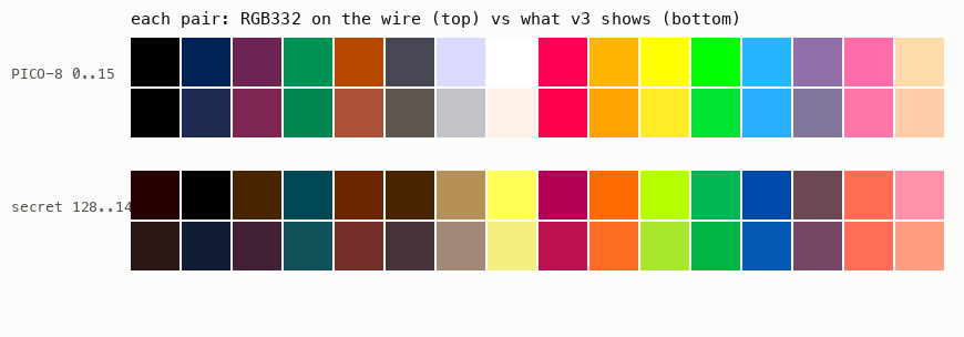
The scanout core became a dozen lines. Core 1 owns the TMDS buffer queues directly - no scanline callback, no colour queues:
while (1) {
    uint32_t *tmdsbuf;
    queue_remove_blocking_u32(&dvi0.q_tmds_free, &tmdsbuf);
    const uint32_t *row = (y < BORDER_ROWS || y >= BORDER_ROWS + SRC_H)
        ? (const uint32_t *)border_line
        : (const uint32_t *)&fb8[disp][(y - BORDER_ROWS) * FRAME_WIDTH];
    tmds_encode_palette_data(row, tmds_palette, tmdsbuf, FRAME_WIDTH, 8);
    queue_add_blocking_u32(&dvi0.q_tmds_valid, &tmdsbuf);
    if (++y == LOGICAL_ROWS) { y = 0; adopt_pending_frame(); }
}
One SRAM trick made the double buffer fit: the framebuffer only stores the 128 active rows (2 x 640 x 128 = 160KB), and the 16 black border rows above and below scan out from a single static 640-byte line. A full 640x160 double buffer would not have fit. Remember that sentence.
I wrote it, sized it, built it, and flashed it. Black screen.
An afternoon of being lied to
What followed was four hours I am writing down so I never repeat them.
The first flash showed nothing but the H7 side reported a healthy
picodvi: 59 fps out SPI5 every second, so the sender was fine. I added a
diagnostic build - boot bars, no SPI link, a blink pattern on the Feather's
LED - and it showed the bars in glorious 3x with the new palette. Scanout
proven. Then every build after that showed nothing at all, including builds
that were supposedly identical to the one that had just worked.
I blamed the one real change I had made in between (moving the DVI interrupt handlers to the other core), reverted it, and the black screen stayed. I blamed the SPI link machinery and staged it component by component, and the screen died before stage one. At my lowest point I was reading meaning into the LED being "solid" versus "off then on later" - and discovered much too late that I had spent several flashes watching the battery charger LED, which glows whenever there is no battery attached, instead of the GPIO-driven D13 next to it. Every observation from that period went in the bin.
Two things broke the spiral. First: flash the last known-good binary and certify the hardware before believing any software theory. The old 2x build went on, the console came straight up, and suddenly the fault was provably in my code and not in a jumper wire that had walked loose during all the BOOTSEL-button gymnastics. Second: stop counting blinks and get real diagnostics out - boot-progress markers on D13, and printf on the Feather's TX pin, where a panic message prints itself by name.
The markers said: reached main, then hung before dvi_init finished. And the map file said why:
__end__       0x2003e9f4     heap starts here
__StackLimit  0x20040000     and ends here
                             = 5,644 bytes of heap
dvi_init allocates its three TMDS scanline buffers with malloc - 3 x
3,840 bytes plus overhead, about 11.6KB. The build had 5,644 bytes of heap.
The second allocation failed, PicoDVI called
panic("TMDS buffer allocation failed"), and the chip sat in a breakpoint
with the LED frozen on. That is the black screen: not the encode, not the
interrupts, not the link. The 160KB framebuffer had eaten the heap.
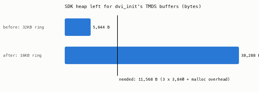
The truly evil part is why it came and went. The SPI receive ring must be aligned to its own size (the RP2040 DMA wraps addresses at a power-of-two boundary), so the linker inserts anywhere from zero to a full ring-size of padding before it - and that padding moves with every unrelated edit. One build has 30KB of heap, the next has 5.6KB, and the difference is a comment you added somewhere. The failure landed on whichever change I shipped next and framed it. The interrupt-core experiment I reverted was, as far as I can tell, never guilty of anything.
Two fixes, both aimed at never debugging this class of bug again:
target_compile_definitions(picodvi_bridge PRIVATE
    DVI_VERTICAL_REPEAT=3
    PICO_HEAP_SIZE=14336   # reserve the TMDS heap at LINK time
)
PICO_HEAP_SIZE reserves the heap as a linker-checked section: if a future
framebuffer squeeze cannot leave 14KB of heap, the build fails with an error
message instead of booting into a silent breakpoint.
And the ring shrank from 32KB to 16KB to pay for it - which promptly broke the link in a brand new way, because the old frame parser waited for a whole wire frame to be resident in the ring before touching it, and a wire frame is 16,512 bytes. You cannot fit 16,512 bytes in a 16,384-byte ring. Bytes flowed, frames never assembled, and the screen showed the world's most confident nothing. The parser is now an incremental state machine - hunt the 4-byte magic, accumulate one 129-byte line, verify its checksum, commit it, repeat 128 times - so the ring only ever needs to hold the few milliseconds of bytes that arrive between polls:
} else {
    // b is the line's checksum byte.
    if ((sum & 0xFF) == b) {
        memcpy(&frame_buf[row * FRAME_W], line, FRAME_W);
    } else {
        bad++;              // keep the previous frame's row
    }
    col = 0; sum = 0;
    if (++row == FRAME_H) {
        in_lines = false;   // next bytes are the next frame's magic
        link_on_frame(frame_buf, FRAME_W, FRAME_H);
    }
}
With both fixes in, the staged diagnostic walked its five stages on the LED, the status cells went green one by one, and at stage five the console appeared - 384x384, true colours, 59fps, and edges that finally survive the monitor's scaler with dignity.
What I kept
Beyond the scanout itself, the afternoon left behind things I intend to lean on:
- The heap is part of the memory budget. If a vendored library mallocs, reserve that heap at link time. A build error is a gift; a boot panic behind a black screen is a tax.
- A size-aligned buffer in bss is a randomiser. Its padding re-rolls on every edit, so failures decorrelate from causes. If a bug appears and disappears with unrelated changes, check the map file before blaming the changes.
- Certify the hardware first. A known-good binary is the cheapest instrument on the bench. Flash it before constructing any theory with the word "contention" in it.
- Know which LED you are watching. The charge LED does not care about your firmware.
- The diagnostic build stays in the tree permanently: boot markers, a staged link bring-up, and printf on the spare UART with panics included.
The 800x600 experiment (a 4x, 512x512 image at a 354MHz overclock - the earlier attempt failed with the stock boot2 clocking XIP flash at an out-of-spec 177MHz, which I only understood this week) is built and waiting for a brave evening. On this monitor the maths says it should lose - 800x600 upscales 2.4x to the panel, non-integer, against 640x480's exact 3x - but the point of an A/B is that the maths does not get the final word. The screen does.
Update, an hour later. The brave evening turned out to be the same afternoon. The 800x600 build synced first try - so the old no-signal really was the flash clock all along - and the maths lost the A/B: the 512x512 image, each console pixel a 4x4 block, reads noticeably crisper than the 3x build despite the non-integer panel scale. Bigger pixels beat purer scaling, at least on this monitor's scaler.
The contrast also improved, which took a minute to explain because the two builds encode identical colours. The answer is in the timing, not the pixels: 640x480@60 is CEA video mode 1, and plenty of sinks assume limited-range video (blacks at 16, whites at 235) for CEA-timed inputs - while 800x600 only exists as a VESA PC mode and always gets full range. PicoDVI is bare DVI with no infoframes to say otherwise, so the monitor guesses from the timing. The 3x build was almost certainly being shown with its blacks quietly lifted the whole time.
One more bug fell out of simply looking at a real game next to its BBS original: the background was dark blue where it should have been black. Two loops up there write 32 exact colours into 256 palette slots, and the order matters - secret colour 129 (darker-blue, 0x111D35) quantises to RGB332 byte 0x00, the same slot as black, so whichever loop runs last owns the slot every black pixel in every game lands on. I had the base palette first. Now the secrets go first and the base palette wins its collisions, and black is black.
The afternoon's last artefact is the tool this post's final image came from. Photographing a monitor never does pixel art justice, so screenshots now come straight off the hardware: the H7 keeps the exact bytes it streams to the Feather in a ping-pong buffer, and the ST-LINK that is already on the bench can read RAM while the console runs. A small script halts the core for a blink (with the watchdog debug-frozen - the first version forgot that and the watchdog rebooted the console mid-screenshot, a very on-brand bug for today), dumps the frame, and renders it through the same palette map the display uses. Pixel-perfect captures, no wires, one second of frame dip:
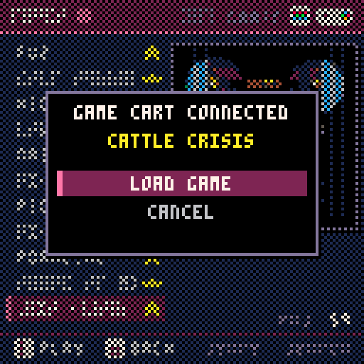
That is a real frame from the running console - the physical cartridge slot announcing a game cart, the launcher dithered behind it, every black pixel actually black.
The 354MHz overclock still has to survive a long soak before this becomes the daily driver, and the 3x build stays one button away as the fallback.